Blog Posted by Ron Jones This is the second, and final, blog of this short series discussing how to properly set up and align a projector with the projection screen. The first part of this discussion is available
HERE. Once you have positioned your new projector correctly in relation to a properly installed projection screen and have also correctly aligned the projector using the available mechanical and optical adjustments, you should always be able to achieve a near perfect rectangular image that correctly aligns with the viewable area of the projection screen.
This blog is intended to expand on the Projector Reviews article titled “The Advantages of Variable Lens Shift, in Placing Your Home Theater Projector” found
HERE. I will discuss projector and screen mounting and projector alignment assuming a ceiling mounted projector, but the same principles apply when the projector is mounted on a shelf or table. This discussion starts off with a very brief overview for the mounting of the projection screen followed by a more detailed discussion on the mounting and alignment of the projector.
Mounting the Screen
When mounting the screen you should use a carpenter’s level to make certain the top and bottom of the screen are truly horizontal and the sides of the screen are also truly vertical You will also need to confirm that the screen surface if perfectly flat. Most of the time this will not be an issue, and a simple visual inspection is sufficient. However, if you do later note problems (such as what should be straight lines appearing curved) with the projected image you can go back and use a plumb bob (and ideally a laser beam) to insure the screen surface is truly planar (in a flat plane). When mounting a fixed frame screen if it looks like, for example, the left edge is not lying in the same flat plane as is the rest of the screen, or if it looks like a point along one edge is bulged, then you will need to add shims between the screen frame and the wall to make a certain the screen’s surface is a flat plane.
Note: In the vast majority of installations having both sides of the screen perfectly vertical is the desired configuration (actually having the entire screen surface perfectly vertical and not tilted outward at the top or bottom). However, in some cases in may be desired to have the screen tilted a little, such as tilted downward just a little. When this setup for the screen is used, the physical setup of the projector must be a little different and this is noted in the section below. This setup can be useful for cases for projectors that do not have a lens shift adjustment and for cases where you need to mount the projector a little lower (i.e., further down from the ceiling) than would normally be required with a perfectly vertical screen.
With a manual pull-down or electric drop-down screen the important thing is to use a carpenter’s level to make certain the screen’s case (housing) is mounted horizontal. Achieving a vertical screen surface is generally not an issue with a manual pull-down or electric drop-down screen as gravity is used to insure the screen hangs vertical.
Setting up the Projector
Once you have mounted the screen, as discussed above, and have determined the correct mounting location for the projector, as discussed in Part 1 of this series, then it is time to move on the actual mounting of the projector. This assumes that you have selected a projector that is compatible with your screen size and location and you have already determined where the projector is to be mounted (i.e., both the ceiling location and the distance from the ceiling down to the center of the projector’s lens). Ceiling mounts for projectors will have an assembly that must be attached to the top of the projector plus a bracket that attaches to the ceiling and in some cases an extension pipe will be needed to lower the projector to the desired vertical position. If your mount uses a fixed length extension pipe then you will need to determine how long it needs to be before attempting to mount the projector.
Note: Many projector mounts, from manufacturers such as Chief and Peerless, use extension pipes that are 1.5 inch diameter that are NPT threaded on both ends. You can save some money by going to a local hardware store and purchasing a ready made pipe, if you can find one of the correct length, or by having a pipe cut to the desired length then threaded. You will the need to paint the pipe to match the color of the mount (typically either black or white).
As discussed in Part 1 of this series, you should have already determined the desired distance from the ceiling down to the center of the projector’s lens. You can determine the needed length of an extension pipe by subtracting from this total desired ceiling-to-lens distance the (1) distance from the center of the projector’s lens to the base of the projector (where the mount will be attached); and (2) the vertical dimension of the projector mount including the ceiling bracket (i.e., when no extension pipe is used). You may be able to use the manufacture’s specs for the mount to determine the total height of the mount, including the ceiling bracket, or simply measure the bracket’s vertical dimension if you have already purchased the mount. If, for example, the vertical size of the mount, including its ceiling bracket, it a total of 4 inches high and the distance from the base of the projector to the center of the lens is 2 inches, then that 6 inch total would be the distance below the ceiling to the center of the lens if no extension pipe were used. If, for example, you have determined you need the lens’ center to be 12 inches below the ceiling then you will need to add an extension pipe that will provide 6 inches of additional vertical drop from the ceiling. You may need to allow a little extra for the length of the extension pipe to allow for the short length of the pipe that fits into the ceiling bracket and also into the top of the projector mount. Also note that some projector mounts are available with adjustable length extensions and these can simplify getting the projector mounted at the correct vertical position. Another projector mounting consideration, especially when using a projector that does not offer a horizontal lens shift adjustment, is to select the mounting location for the projector such that the center of the projector’s lens will located directly back (at a 90 deg. angle) from the horizontal center of the screen. One way to do this is select a candidate projector mounting point on the ceiling that you have measured to be the correct distance (i.e., projector-to-screen throw distance) back from the screen and what you estimate to be centered with the screen. Next measure the distance from this candidate mounting point to each of the top corners of the screen. If the measured distance is longer to one corner than to the other then you will need to move the candidate mounting point on the ceiling a little to one side or the other until your find the point that is an equal distance from each top corner of the screen. Once you find the point on the ceiling that is centered with the screen, then mark that point on the ceiling (e.g., using a small piece of masking tape). Next look at your projector and determine if the lens’ position is centered, or not centered, side-to-side with the projector’s cabinet (actually with the center of the projector mount). If the projector has its lens in the center then the ceiling bracket can be mounted directly centered with the point you marked on the ceiling. However, if the projector’s lens is not centered with the projector’s cabinet, then you will need to measure how far off from the cabinet center the lens is located (typically less than 4 inches). Now remember that we want is to get the lens centered with the screen and if the lens is offset to one side or the other then the point where the mount will be attached to the ceiling will need to be offset by the same amount in the opposite direction. For example, with the projector in its inverted position and with the mounting bracket attached and facing upward, if the lens is positioned two inches to the right of the center of the projector (i.e., the center of the mount) then the ceiling bracket for the mount will need to be positioned two inches to the left of the center position previously marked on the ceiling. For projectors that offer a horizontal lens shift adjustment, mounting locations that are not centered with the screen can be accommodated, but better image quality often results when the projector is centered, or only a short distance off-center, and no more than modest lens shift is required. For the following discussion I am generally going to assume the projector location is centered with the screen unless otherwise noted.
Note: While projectors offering a vertical lens shift adjustment may be able to provide great flexibility in the vertical position where the projector may be mounted, generally the best image quality will be obtained when only minimal vertical lens shift is required. For many projectors offering a wide range vertical lens shift adjustment, such as those from Epson, JVC, Sony, etc., using a mounting location nearly level with the top of the projection screen's viewable area works well.
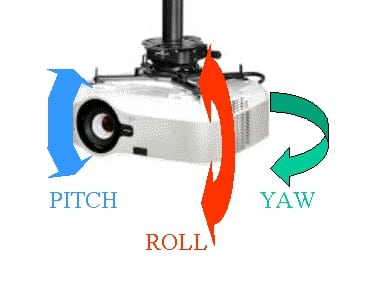
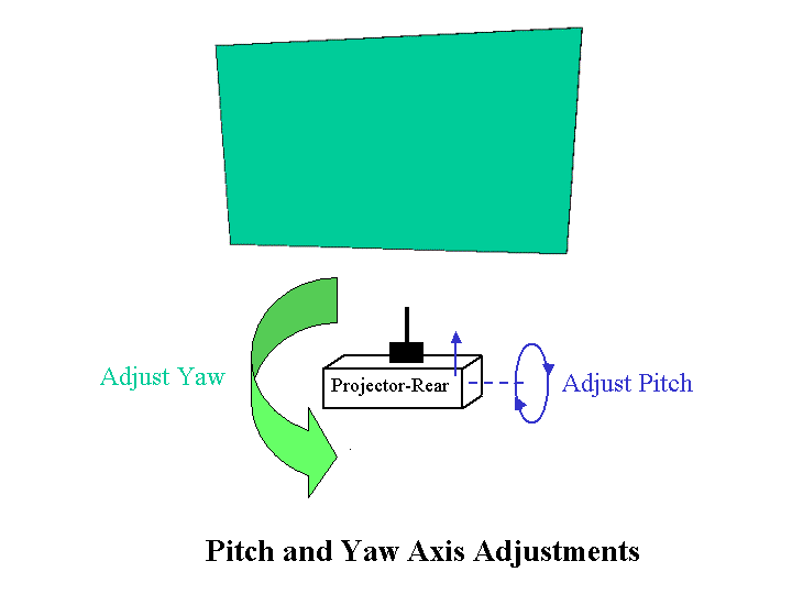
Before actually mounting the projector to the ceiling, I suggest you set the projector on a table, connect the power cord and turn the projector on. Bring up the projector’s main menu and focus the image. If the projector has lens shift adjustments (either just vertical or both vertical and horizontal) set these to their center position. Depending on your projector, these may be mechanical adjustments using knobs or wheels on the projector’s cabinet or they may be motorized adjustments that can be controlled with the remote control via the projectors’ menus. Finally, you will need to access the projector’s menus to set the projector for a ceiling mounted, front projection configuration (this will result in an inverted image when the projector is sitting upright on a table). Once you have done the above recommend steps to configure the projector, turn the projector off and after the projector’s cooling fan stops, then remove power from the projector and turn it over such that the base of the projector is facing upward. You are now ready to go ahead and physically attach the mounting bracket to the base of the projector. Some projectors may require you remove the “feet” on the projector base before attaching the mounting bracket. Follow the instructions provided with the projector and with the ceiling mount that you have selected, to attach the mounting bracket to the base of the projector as well as install the ceiling bracket along with any needed extension pipe. Finally lift the projector, with its attached bracket, onto the mating bracket from the ceiling bracket (or on the bottom of the extension pipe). Secure the brackets, as per the instructions provided with the projector mount, such that the projector safely secured in place. Once the projector is mounted from the ceiling and you have verified that it has the correct drop distance down from the ceiling (i.e., to provide vertical offset to the screen’s position that is compatible with your specific projector model as discussed in Part 1 of this series), then it is time to adjust the projector mount to level up the projector and center the image on the screen. Before you power up the projector you should do a basic setup to mechanically adjust the projector on its mount to approximately the ideal position on all three axis (i.e., pitch, roll and yaw – see the figure below). You should adjust the projector mount so that the projector appears visually to be level, both left-to-right and front-to-back. Next the projector needs to be pointed toward the center of the screen (assuming the projector has been mounted centered with the screen as described above). You can rotate the projector (‘yaw’ axis) until it appears to approximately be pointed at the center of the screen.
Note 1: If you are using a projector that offers a horizontal lens shift adjustment and you have mounted the projector toward the right or left of the screen’s centerline, then the front of the projector (i.e., actually the projector’s lens) should be kept parallel to the screen’s surface, rather than attempting to point the projector’s lens toward the screen’s center.
Note 2: If you have mounted the screen with it tilted vertically then you will need to adjust the pitch axis of the projector mount by a similar amount of tilt in order to keep the front of the projector parallel to the surface of the screen. For example, if the top of the screen is tilted 3 degrees outward (toward the viewers) then the pitch of the projector should be adjusted to provide a 3 degree upward tilt (i.e., with the front of the projector tilted upward a little relative to the back of the projector). If the projector being used with this screen mounting arrangement does not have a vertical lens shift adjustment, then it will need to be mounted lower (i.e., further down from the ceiling). For example, with a 3 degree tilt and if the projector were mounted 10 ft. back from the screen, the projector would need to be mounted approx 6 1/4 inches lower than if the screen were mounted truly vertical. Using such an arrangement can be useful for projectors that have a large vertical offset (as described in Part 1 of this series).
There are a few approaches for proceeding with the mechanical and optical alignment of the projector that will work and installers with a lot of experience may be able to take shortcuts that save time but are perhaps more difficult for first time installers. Therefore, I have decided to first present an approach that should result in an initial mechanical alignment that will probably get you fairly close to the correct pitch, yaw and roll final alignment positions. The second approach results in a more coarse initial mechanical alignment that some, perhaps most, experienced installers will find sufficient to get them ready to commence the more accurate final optical and mechanical alignment.
Initial Mechanical Alignment: Approach 1 –
Use a tape measure to locate the horizontal center of the screen and then place a small piece of masking tape on the wall (or screen frame) just above the top of the screen. Next standing behind the projector sight along the centerline of the projector while rotating the projector (i.e., yaw axis) such that center of the screen lines up with the centerline of the projector. After this is accomplished you will need to more precisely level the projector front-to-back (the ‘pitch’ axis) and left to right (the ‘roll’ axis). A bubble level can assist in getting the projector level on both the pitch and roll axis. It is where the mounting bracket is attached to the projector that needs to be level and depending on the shape of the projector’s cabinet this may a little difficult to accomplish using a bubble level. This completes the initial mechanical adjustment of the projector mount for the most common case where the projector is mounted directly back from the center of the screen and the screen surface is vertical and not tilted from top to bottom. This is intended to get you close to the projector’s final mounting position, but final adjustments will need to be made, as discussed below, once the image is being projected onto the screen.
Note: If you have mounted the projector with a horizontal offset relative to the screen’s center and plan to use the projector’s horizontal lens shift to center the image, then you should sight along the center line of the projector and adjust the yaw axis of the mount to a aim the projector to a point with the same horizontal offset from the screen’s center position. The key thing is to keep the front of the projector parallel to the screen.
Once you have completed the above the steps you will need to correct for any geometry issues that cause the projected image to not be a near perfect rectangle when centered on the screen. See the section below on Final Optical/Mechanical Alignment.
Initial Mechanical Alignment: Approach 2 –
With this approach the projector does not have to be perfectly level, on the pitch axis, nor does the screen have to be perfectly vertical. What must be correct is to make certain the projector’s front (actually the lens) is perfectly parallel to the screen (for both the vertical and horizontal axis). However, the screen surface must be a perfectly flat plane and projector mount must be adjusted to make certain the lens is parallel to the surface (i.e., plane) of the screen. Experienced installers may just set the projector mount’s pitch, roll and yaw axis adjustments visually then rely on getting these adjustments corrected as part of the final Optical/Mechanical alignment, described below. With this approach you do not need to use a bubble level on the projector. However, with a fixed frame screens you will need to use a carpenter’s level to make certain the top of the screen frame is level (as described in the section above for mounting the screen).
Final Optical/Mechanical Alignment
Now connect the power cord and a signal source to the projector and turn the video source and the projector on. After the projector boots up, use the projector’s remote control to switch to the correct video input and an image should be displayed.
Note: If the projector has a built-in x-y grid test pattern that can be displayed, that can be useful for the adjustments to get the image geometry correct. If your projector does not offer such a built-in test pattern then playing a DVD or Blu-ray test disc with a x-y grid pattern can be useful. While such test patterns can be useful, they are not essential and regular video programs can be used instead.
If when doing the following optical/mechanical alignment you find that the edges of the projected image actually appear curved, or when projecting a x-y grid pattern you find that any of the lines appear curved, then you screen is not perfectly flat and you will need to address this issue with the screen's mounting.
Projectors WITHOUT Lens Shift Adjustments
For projectors lacking any lens shift adjustments, then if you have:
1- mounted the screen correctly, as describe above, and have
2- mounted the projector at the one and only correct vertical and horizontal position relative to your screen’s size and location
Note: If either before or after mounting your projector you determine that is not (or will not be) correctly centered with the screen or if you need to move the projector just a few inches (e.g., less than 4 inches) closer or further from the screen, then several projector mount manufacturers offer a "Lateral Shift Bracket" that allows the projector to be offset, horizontal, up to a few inches from the center of the ceiling bracket/extension pipe. This can be especially useful for projectors that do not offer a horizontal lens shift adjustment, as the lateral shift bracket allows some 'fine tuning' of the projector's lateral position.
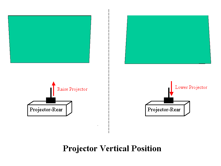
Then you should be able to use the projector’s zoom lens to obtain the correct image size and use the projector mount’s roll adjustment to level the image and the mount’s pitch and yaw adjustments to center the image on the screen. If after doing these adjustments, and focusing the projected image, you find the image geometry is not a near perfect rectangle then the projector is not mounted at the correct location relative to the screen’s location. Remember that geometry issues, when using projectors that lack lens shift adjustments, can only be corrected by relocating the projector or correcting the screen’s location or mounting (i.e., top/bottom level horizontal and sides vertical with the screen surface flat without any bows, bulges, etc.). For home theater use, the projector’s electronic keystone adjustment should never, ever be used to correct geometry issues as it degrades the projected image. If the projector is simply mounted too high or too low, relative to the screen’s position, that may be easy to correct by using a longer or shorter extension pipe between the ceiling bracket and the projector’s mount assembly. The following illustration shows the image geometry issues that are created when the projector has been mounted too low or too high and the direction the projector will need to be moved (i.e., either raised or lowered) to correct the geometric distortion.
Projectors WITH Lens Shift Adjustments –
You should be starting with the horizontal lens shift adjustment set in its center position (your projector may have either just a vertical lens shift adjustment or both vertical and horizontal). Use the vertical lens shift adjustment to approximately center the image on the screen. Use the projector’s zoom lens to obtain approximately the correct image size for your screen. Focus the lens to provide a sharp image. Adjust the projector mount’s roll adjustment such that the top and bottom edges of the image are approximately horizontal and aligned with the top and bottom of the screen and also the right and left edges of the image are vertical and aligned with the sides of the screen. You will likely need to repeat this adjustment after doing the following adjustments. The following illustration shows the effect of the roll adjustment.

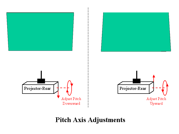
For projectors that have a vertical lens shift adjustment you will need to find the right combination of the projector mount’s pitch adjustment and the projector’s vertical lens shift adjustment such that the sides of the projected image are parallel with each other. The following illustration shows the image geometry issues created with an incorrect pitch adjustment and the direction of movement to the projector’s pitch that is needed to correct these geometry issues. Any changes to the pitch adjustment should be made in very small increments then the vertical lens shift set to vertically center the image on the screen. You will likely need to repeat these two adjustments a few times to zero in on the correct combination that will produce a image with the right and left edges that are parallel to each other.
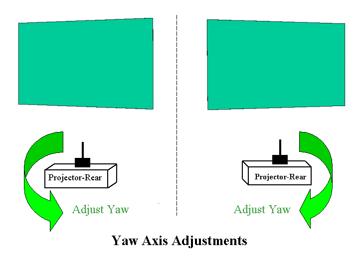
For projectors that have a horizontal lens shift adjustment you will need to find the right combination of the projector mount’s yaw adjustment and the horizontal lens shift adjustment such that the top and bottom edges of the projected image are parallel to each other. For those projectors with a horizontal lens shift adjustment the illustration below shows the image geometry issues created with the incorrect yaw adjustment and the direction of movement to the projector’s yaw that is needed to correct the geometry issue. Any changes to the yaw adjustment should be made in very small increments then the horizontal lens shift set to horizontally center the image on the screen. You will likely need to repeat these two adjustment a few times to zero in on the correct combination that will produce a image with the top and bottom edges that are parallel to each other.
Note: If your projector does not have a horizontal lens shift adjustment then you will need to just use the mount’s yaw adjustment to center the image on the screen. If either before or after mounting your projector you determine that is not (or will not be) correctly centered with the screen. then several projector mount manufacturers offer a "Lateral Shift Bracket" that allows the projector to be offset, horizontal, up to a few inches (e.g., 4 inches) from the center of the ceiling bracket/extension pipe. This can be especially useful for projectors that do not offer a horizontal lens shift adjustment, as the lateral shift bracket allows some 'fine tuning' of the projector's lateral position.
In the real world you will most likely find that as a starting point for the optical alignment you will have more severe geometric errors in the projected image due to a combination of pitch, roll and yaw errors. The following illustration shows the type of geometry you can get with a combination of pitch and yaw errors.
You will probably need to repeat the above described roll, pitch and yaw adjustments, in combination with the projector’s lens shift adjustments, two or three times to get the ideal rectangular image perfectly centered on the screen. You will also need to make final adjustments to the projector’s zoom and focus in order to create a ‘ideal’ image. The projector’s electronic keystone adjustment should never, ever be used to correct geometry issues as it degrades the projected image.
Note: Some of the above material is based on information provided by Mark Haflich.
__________________________________
September is expected a very BIG month for news concerning home theater projectors, screens and accessories as the annual CEDIA Expo trade show is being held 25-28 September. Projector Reviews will be reporting from the show. I plan to post a CEDIA Preview blog earlier in September, then provide daily blogs directly from the show.